
The CAN bus communication network, using the OBD2 protocol, is standard in most vehicles from 2002 onwards. This means that the primary way to communicate the status of components such as sensors, actuators, ECUs, and others is through CAN bus. However, not all vehicles or trucks have this type of network for all sensors and actuators. Some use a LIN bus network to control steering wheel controls, comfort modules, and other actuators. Typically, the connection runs from the BCM to its LIN input. Each module is then called a LIN slave, and the BCM itself is the LIN master, communicating with the ECM, TCM, and other components via CAN. Graphically, it would look like this: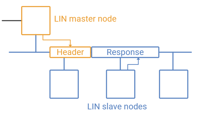
Now, in the event of a failure in any LIN network frame, I will observe that the modules associated with that frame remain powered on. This is because the BCM programming, upon detecting the lack of response from the slave, generates an automatic emergency response, which will continue until the LIN slave responds correctly again. To simulate this, simply disconnect the LIN cable, which supplies between 7 and 8 volts, from any of its modules. However, to command a direct LIN response, it is necessary to connect a LinBus Daughter Board to the network. This board allows me to send information, simulating a slave, and control the parameters to observe the behavior of the actuators or sensors according to the following diagram: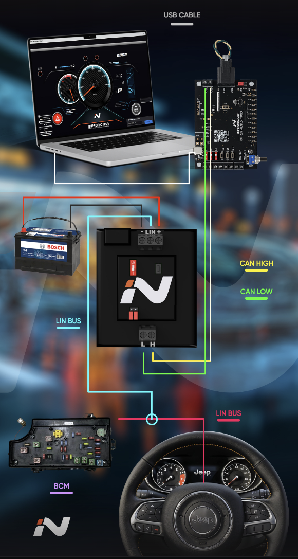
Finally, this will allow you to identify the data being generated as a LIN response, the Master headers when querying each module, and the CAN network messages, which vary according to the simulated behavior of each module. This will not only allow you to generate an advanced diagnosis, but also generate a reverse engineering process to acquire data from each vehicle and each module.