
To understand how to connect the Inpronic 250k to 500k converter to adapt motors like the 60 series with DDEC5 computers (250k) to control units like the New Cascadia with a 500k input to the control unit's network, we need to understand the function of the gateway.
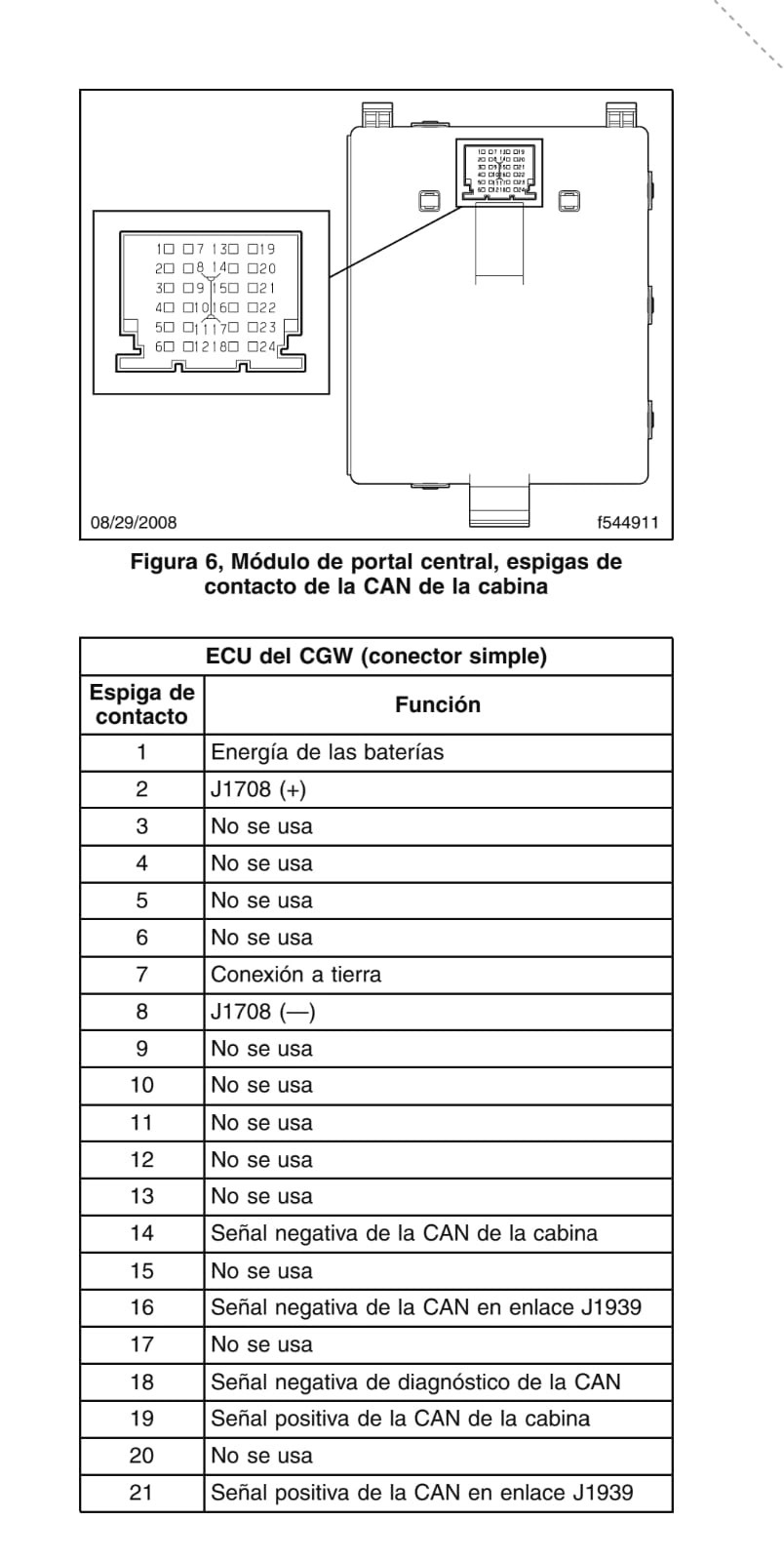
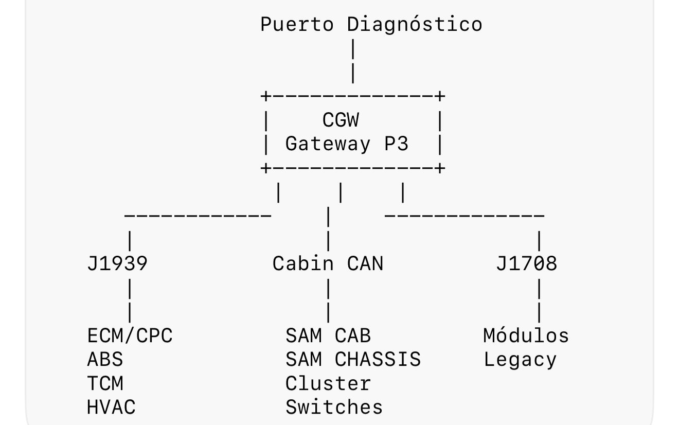
Remember that the gateway takes the 500k output from the Inpronic converter. To do this, the CAN high and CAN low outputs of the 500k output must be connected to the C and D inputs of the diagnostic port. This input then enters the gateway through the corresponding pins, according to the diagram for your specific gateway. From there, lines run directly to the J1939 line of the control unit after the gateway, and from there to the instrument cluster. This completes the connection, ensuring 100% functionality. A diagram of the inputs and corresponding logic is provided below.