


Modern heavy-duty vehicles are no longer controlled only by simple switches and direct wires. Today, many cab functions are connected to electronic networks, where switch commands, operator requests, and status signals are transmitted through J1939 CAN-BUS communication.
This change has created a new challenge for technicians, builders, and retrofit specialists:
How do you connect modern engine control requirements with cab switches, dashboards, and custom control panels?
In older systems, a switch could often be wired directly to a circuit. The driver pressed a button, the circuit closed, and the function activated. But in modern electronically controlled engines, especially in heavy-duty applications, the Engine Control Module often expects specific low-side signals or J1939-based logic to confirm what the operator is requesting.
That means the issue is not only electrical.
It is also communication-based.

What Is a Cab Switch Interface?
A cab switch interface is a system that helps connect operator controls inside the cab to the engine or vehicle control system.
These controls may include:
- Parking brake
- Clutch brake
- Service brake
- Cruise control enables
- Cruise set
- Cruise resume
- Engine brake or retarder levels
- Fan override
- PTO-related commands
- Auxiliary outputs
In a modern vehicle, these controls may not always be connected directly to the ECM as traditional high-current switch circuits. Instead, the cab may send switch status over the J1939 network, where the information must be read, interpreted, and converted into the correct physical output signal.
That is where a J1939-based cab switch interface becomes important.
What Does Low-Side Output Mean?
A low-side output is a ground-activated signal.
Instead of sending power to activate a function, the module provides a controlled ground path that the ECM can recognize. Many engine control systems use this type of input for switch-based functions.
For example, an ECM may be programmed to detect a grounded input for:
- Clutch switch activation
- Service brake input
- Parking brake input
- Cruise control enable
- Cruise set or resume
- Engine retarder selection
- Fan override
A clean low-side signal is important because the ECM needs a stable and predictable electrical condition. If the signal is unstable, noisy, or incorrectly wired, the ECM may ignore the command or interpret it incorrectly.
How a J1939 Cab Switch Interface Works
A J1939 cab switch interface follows a logical process.
First, it monitors the J1939 CAN network for cab-related switch messages or status data. Then, it filters and evaluates that information. Based on predefined logic rules, it decides whether a physical output should be activated or deactivated.
The process can be understood in four steps:
- Cab switch data is transmitted over the J1939 CAN network.
- The controller reads and filters the incoming CAN data.
- Logic rules determine which outputs should activate.
- Opto-isolated low-side outputs provide ECM-ready ground signals.
This approach allows the physical outputs to reflect the actual digital state of the cabin, rather than relying only on direct wiring assumptions.

How the INPRONIC Control Switch Fits Into This Process
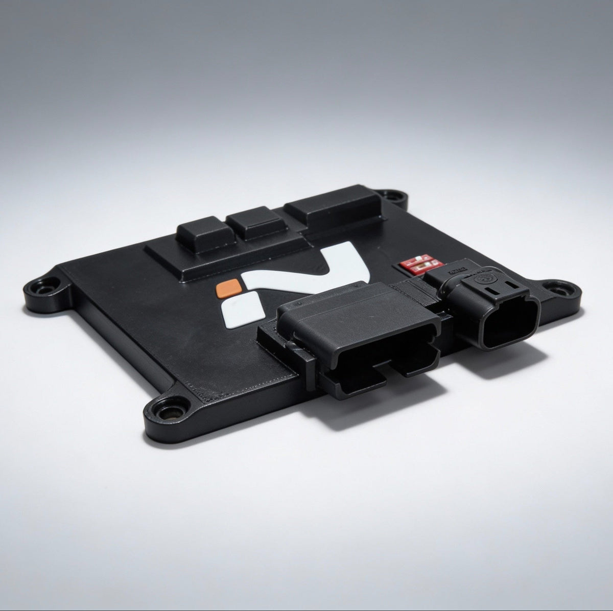
The INPRONIC Control Switch is designed as a J1939 CAN-based Cab Switch Interface Controller for modern engine control integration.
It monitors J1939 cab messages, filters switch and status data, applies rule-based output logic, and activates 12 opto-isolated low-side outputs.
This makes it useful for applications where digital cabin data must become clean ECM-ready grounding signals.
Typical output assignments include parking brake, clutch brake, service brake, engine retarder selection, cruise resume, cruise set, cruise enable, fan override, and auxiliary user-defined outputs.
Rather than acting as a simple relay board, the Control Switch reads and interprets J1939 information, then activates outputs based on logic.
This helps reduce harness complexity and provides a cleaner way to connect modern cab switch data with engine ECM requirements.

Share:
Understanding OBD-II and J1939 Communication CAN BUS Multiplex Trainer